What is an RF Phase Shifter?
An RF Phase Shifter is a component that is used to adjust the phase angle of a given RF signal while leaving the amplitude unchanged. Phase is the position of a wave at a point in time on a waveform cycle and lies somewhere between 0 and 360 degrees.
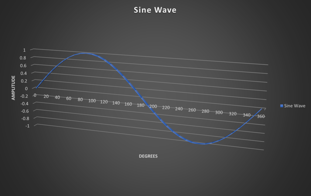
Figure1: Sine Wave
Generally, in applications for Phase Shifters the interest lies in phase difference more than it does in phase. When comparing two waves, the phase difference or phase angle is measured in degrees and describes how much one wave leads or lags another wave. Below are 2 examples where one wave leads the other by 90 and 180 degrees respectively.
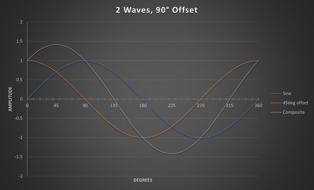
Figure 2: 2 waves, 90deg offset
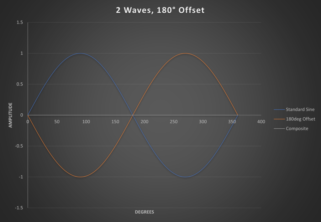
Figure 3: 2 waves, 180deg offset
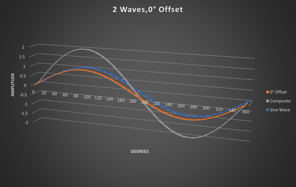
Figure 4: 2 waves, 0deg offset
Two signals that have the same frequency and different phases are considered out of phase. Two signals with the same frequency and no phase difference are considered in phase. Phase shifter components have a specified phase range which defines how much the phase of the signal can be adjusted. Within that phase range one of the waves can be adjusted using the phase shifter to align it with the other wave. The composite signal can be cancelled out in full or partially or stronger, depending on the offset of the two signals. The above figures show the resulting composite waves at an offset of 0°, 90° and 180°. The composite wave of 2 signals with the same phase and amplitude is a much stronger signal as opposed to the canceled-out wave when offset by 180°, see figure 2.
Here are some of the properties of a phase shifter to consider:
- Type of Phase shifter
- Frequency Range
- Phase Shift Range
- Insertion Loss
- Return Loss
- Phase Accuracy
Types of Phase Shifter
There are different types of phase shifters available. The fixed phase shifters have a set value of phase shift, for example 30degrees or 60degrees. Variable phase shifters phase shifters let you adjust the phase in steps or continuously variable.
There are three types of variable phase shifters defined by how they are controlled, mechanical, digital and analog, using voltage.
Digital Phase Shifter
The programmable Digital phase shifters can be controlled using a computer. They exhibit fast switching speeds and flat phase performance over the defined frequency range. They generally have a higher VSWR and Insertion Loss than mechanical phase shifters. These phase shifters are set in steps and the step size depends on the number of bits, or integrated phase shifters. The higher the number of bits, the smaller the step size and the higher the number of phases. For example, a 6-bit phase shifter will cover the entire range from 0 to 354.375° in 5.625° steps, which allows 64 distinct phases. The smaller the step size, the higher the complexity and with that the Insertion Loss of the phase shifter. Below figure illustrates a 2-bit phase shifter using SPDT switches and also one using PIN diodes and transmission delay lines.
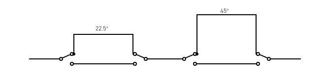
Figure 5: 2-bit SPDT Switches Circuit
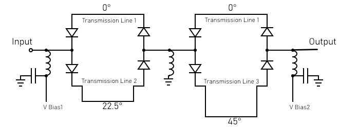
Figure 6: 2-bit PIN Diodes and Transmission Lines Circuit
Analog Phase Shifter
Analog Phase Shifters often are adjusted using a control voltage. Phase adjustment is continuously variable which allows for a very precise phase setting. The phase shift change is dependent on the voltage level applied to the circuit. Below is a circuit of an analog phase shifter using varactor diodes that change capacitance with the control voltage.
Analog phase shifters generally have lower insertion loss than digital phase shifters. Unlike the digital phase shifters, phase does not change flat over frequency.
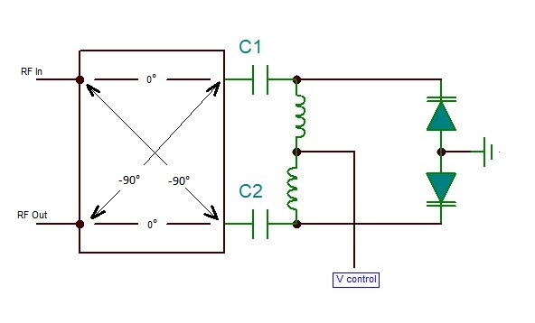
Figure 8: Analog Phase Shifter Circuit
Mechanical Phase Shifter
A mechanical phase shifter is designed to mechanically extend the transmission line. This is usually done through a trombone design that when adjusted lengthens or shortens the transmission line between the input and output.
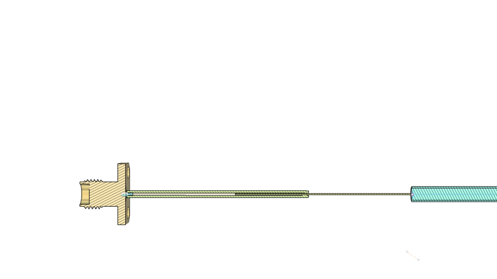
Figure 9: Trombone Style Adjustment
The adjustment can be done as simply as with an adjustment knob or remotely using a motor drive. Phase changes monotonously and continuously variable. The maximum phase adjustment is directly related to the change of length of the transmission line.
This type of phase shifter offers a higher power rating, lower VSWR and insertion loss. These are often larger than the digital and analog phase shifters. The change of phase is not flat over the frequency, but it changes proportionally over the frequency range. Below is a chart that shows the relationship between frequency and phase.
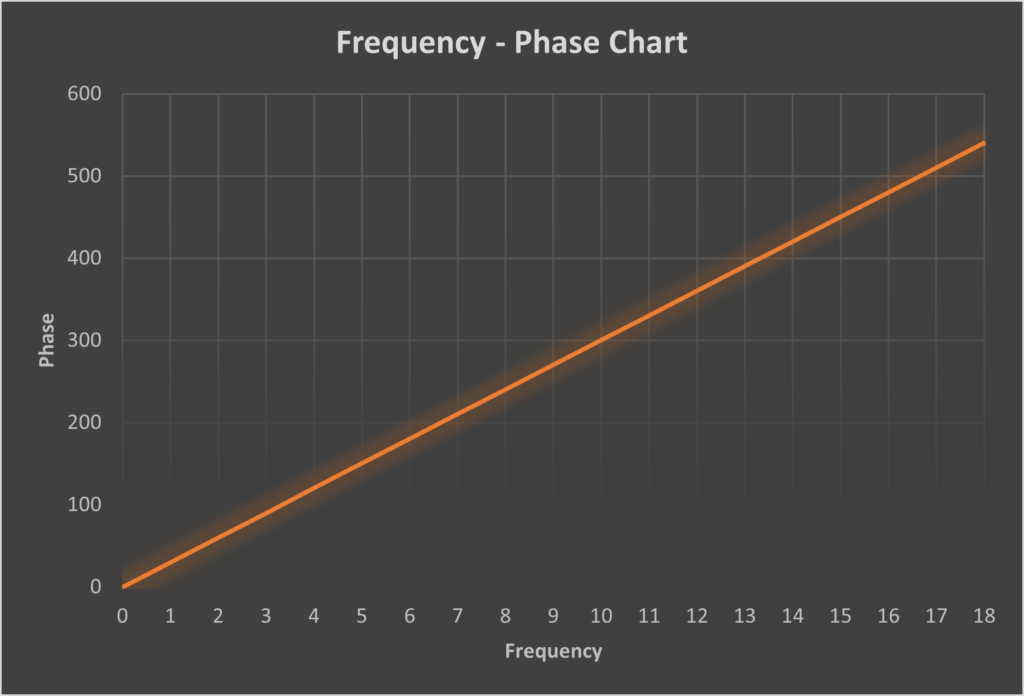
Figure 10: Frequency Phase Chart
This is the type of phase shifter Impulse Technologies manufactures with frequency ranges from 10MHz up to 40GHz. The phase range available is either 0°-360°, 30° per GHz or 60° per GHz. It is available with 2 different adjustment options, a standard knob or a digital dial. The advantage of the digital dial is that it provides the phase change at 1 GHz which can easily be scaled up to the frequency of interest by multiplying it with that frequency in GHz.
Applications of a Phase Shifter
So, what are phase shifters used for? Basically, they are used in devices where the phase angle of an RF signal needs to be changed. Common applications are phase modulators, RF test equipment, frequency up-converters, TR Modules and Phased Array Antenna Systems.
Figure 10 below is an example of a phased array antenna system to illustrate the use of a phase shifter. The signal from the amplifier goes through the attenuator and phase shifter for each element to align amplitude and phase to each other to control the direction and the shape of the beam. By adjusting the phase for each antenna, a wave front can be created that moves at a desired angle from the phased array antenna system. These systems are used in radar systems but now also in 5G MIMO applications. Phased array antennas are also used in automotive radars for the purpose of traffic control and collision avoidance.
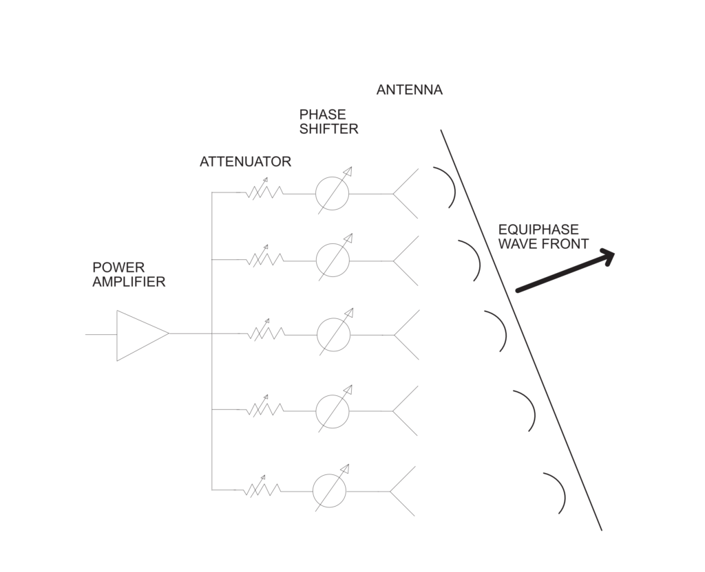
Figure 11: Phase Array Antenna System
Looking for related RF fundamentals? You may also be interested in our article “What is an RF Attenuator?” which explains how attenuation is used alongside phase control in RF systems.